
Testing Reachability and Latency with Ping
Master ICMP echo testing across local and routed networks. Learn how to interpret round-trip time latency, calculate packet loss percentages, inspect Time to Live (TTL) hop counters, and differentiate between network timeouts and host unreachability.
When an employee reports that a file share is unreachable or cloud applications feel sluggish, the very first command every network engineer runs is ping. Created in 1983 and named after the sound of naval sonar pulses, ping remains the most dependable first-response diagnostic tool in computer networking.
Underneath its simple command-line interface, ping leverages the Internet Control Message Protocol (ICMP) to measure round-trip network latency, detect physical packet loss, and verify path integrity hop by hop. A single four-packet ping test can reveal whether a problem lies in local cables, intermediate routers, or distant firewalls.
Unlike standard application traffic that relies on TCP handshakes or UDP streams, ICMP operates directly at the network layer. This allows network administrators to verify physical layer and IP routing connectivity even when user-space applications or web services are completely offline.
In this practical tutorial, you will generate ICMP echo traffic across switches and routers, analyze TTL hop counters to determine device operating systems, and learn how to differentiate between request timeouts and destination unreachability.
Network Architecture Plan
| Segment | Interface | Subnet / Address | Functional Role |
|---|---|---|---|
| Source Workstation | FastEthernet0 | 192.168.1.10/24 | Ping Initiator Host |
| Local Switch | Fa0/1 - Fa0/2 | Layer 2 | Local Segment Forwarding |
| Office Router | Gi0/0 - Gi0/1 | 192.168.1.1 / 10.0.0.1 | Intermediate Gateway |
| Remote Branch Server | FastEthernet0 | 10.0.0.50/24 | Remote Target Host |
How Ping Operates
The ping utility operates using two fundamental message types defined in RFC 792: Type 8 (Echo Request) and Type 0 (Echo Reply).
When you execute a ping command, the source operating system formats an ICMP Echo Request packet containing a sequence counter, a unique identifier, and a payload of test bytes (typically 32 or 64 bytes).
The destination computer receives this packet and immediately reflects it back as an ICMP Echo Reply. By comparing the transmit timestamp with the arrival timestamp, ping calculates the exact round-trip time in milliseconds.
Because ICMP messages do not use transport layer port numbers like TCP port 80 or UDP port 53, the operating system uses the ICMP Identifier and Sequence Number fields to match incoming replies with their corresponding outbound requests.
Unlike web browsers or email clients, ICMP does not establish a TCP connection or send UDP datagrams. ICMP packets are encapsulated directly inside IPv4 packets (using IP Protocol number 1).
This direct encapsulation allows ping to test pure Layer 3 reachability with minimal host processing overhead.
Because ping measures round-trip time rather than one-way transit time, network congestion on either the forward path or the return path will increase the reported latency.
Protocol Reality: Because ICMP runs directly over IP without TCP handshake overhead, it tests raw Layer 3 reachability even when higher-level services like HTTP or SSH are stopped on the destination.
Measuring Local Latency
Open the command terminal on Source Workstation and ping the local default gateway router at 192.168.1.1.
Notice the millisecond response times and packet statistics reported for each of the four test probes.
In local area networks, consistent latency values are just as critical as low numbers. Variations between ping times are known as jitter, which severely degrades real-time applications like Voice over IP (VoIP) calls and video streaming.
Breaking Down the Echo Reply Fields:
Reply from 192.168.1.1: Confirms that the target device received the request and sent back an authentic Echo Reply.bytes=32: The payload size carried inside the ICMP data segment.time=1ms: The round-trip time (RTT). On a local wired Ethernet switch, response times between 1ms and 2ms indicate a clean physical wire with zero queue congestion.TTL=255: The Time to Live counter set by the responding operating system. A value of 255 indicates an enterprise network appliance running Cisco IOS.Lost = 0 (0% loss): Proves complete bidirectional data transmission with zero dropped frames.Field Tip: If you observe 100ms+ latency on a local switch ping, check for physical duplex mismatches (half duplex vs full duplex) or bad copper crimps causing frame check sequence errors.
Understanding the TTL Counter
Every IPv4 packet contains an 8-bit header field called Time to Live (TTL). Operating systems set this field to an initial default when generating a packet.
Every time a packet crosses a Layer 3 router hop, the router decrements the TTL counter by exactly 1 before forwarding the frame. If the TTL value ever drops to 0, the router discards the packet and sends an ICMP Time Exceeded message back to the sender.
This hop countdown mechanism prevents lost packets from circulating forever in infinite routing loops.
Linux / Android / UNIX:       Initial TTL = 64
Windows Workstations/Servers: Initial TTL = 128
Cisco IOS / Network Routers:  Initial TTL = 255
Solaris / AIX Mainframes:     Initial TTL = 255
Calculating Routing Distance from TTL:
Because standard operating systems use well-known initial TTL values, network engineers can calculate the exact number of router hops between two endpoints.
For example, if you ping a server and receive TTL=54, you can infer that the target is a Linux machine (initial TTL 64) sitting exactly 10 router hops away ($64 - 54 = 10$).
Switches operate at Layer 2 and forward frames based on MAC addresses, so switches never decrement the IP TTL field.
This exact mechanism forms the technical foundation of the traceroute command, which intentionally sends packets starting with TTL=1, TTL=2, and TTL=3 to discover every intermediate router gateway along the path.
Hop Limit Fact: The IPv6 protocol replaced the name Time to Live with Hop Limit to reflect its true purpose: counting router decrements rather than real clock seconds.
Timeout vs Unreachable
Not all ping failures mean the same thing. Learning to read the exact diagnostic error message prevents hours of blind troubleshooting.
In this phase, we compare two classic network failure modes: the silent Request timed out versus the active Destination host unreachable.
Comparing Failure Modes:
192.168.1.1) actively generated an ICMP Type 3 error message back to the workstation. The router inspected its routing table, found no matching route for 172.16.5.0/24, and immediately notified the sender that forwarding was impossible.Notice the critical difference: a timeout means no device answered, while unreachable means a specific router answered to report a missing path.
Knowing whether a router reported unreachable or simply timed out tells the engineer whether to examine the routing table or check the target server host firewall.
Firewall Gotcha: Modern Windows Server operating systems block inbound ICMP echo requests by default in Windows Defender Firewall. A server can be serving web traffic perfectly while still failing ping tests.
Testing Remote Hosts
Now test end-to-end communication across the entire lab topology. Open the terminal on Source Workstation and ping the Remote Branch Server at 10.0.0.50.
This test crosses the local switch, traverses the gateway router, and reaches the remote subnet.
Watch the reported round-trip time and compare the resulting TTL value against the local gateway test from Phase 2.
Verifying Routed Hop Traversal:
Reply from 10.0.0.50: Confirms full two-way reachability across the router boundary.TTL=63: The Remote Server is a Linux host that initialized its TTL to 64. When the reply packet crossed the Office Router back toward our workstation, the router decremented the TTL from 64 to 63.time=3ms - 4ms: Shows a slight latency increase compared to local switch pinging (1ms). Crossing router interfaces and routing lookups adds a few milliseconds of forwarding overhead.ping -f -l 1472). If any link on the route has an MTU lower than 1500 bytes, routers drop the frame and reply with an ICMP Fragmentation Needed error.The 0% packet loss proves that all physical cables, IP addresses, and routing tables in our network are fully operational.
Continuous Testing Tip: On Windows workstations, use ping -t to run an ongoing ping stream while wiggling cables or rebooting switches. Press Ctrl+C to display the final packet loss summary.

Related Network Labs
Continue your network simulation practice with these recommended labs.
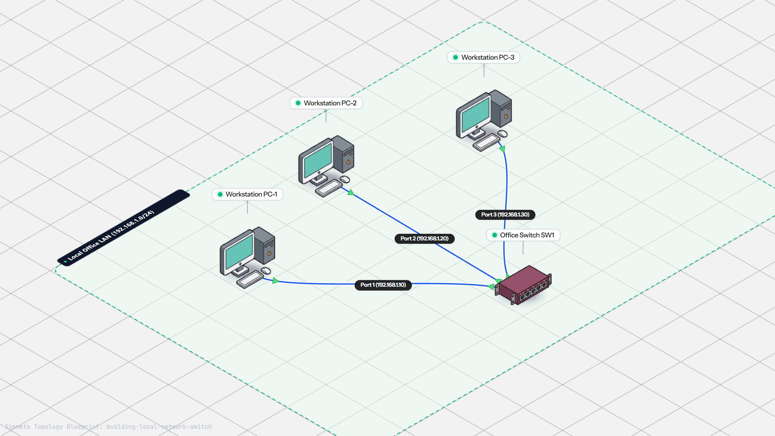
Building a Local Office LAN with a Switch
Setting Up a Local Web Server
VLAN Trunking with 802.1Q
Preventing Loops with Spanning Tree
Securing Switch Ports with Port Security
Bundling Switch Uplinks with LACP EtherChannel
Inter-VLAN Routing with Router-on-a-Stick
Dynamic Routing with Single-Area OSPF
Gateway Redundancy with HSRP Failover
Filtering Traffic with Extended ACLs
Connecting LAN to Internet with NAT
Resolving Domain Names with Local DNS
Stopping Rogue DHCP with Snooping
Connecting Two Switches with an Access Uplink
Configuring Static IP on Workstation
Inspecting ARP Cache Tables
Setting Up DHCP Static Reservations
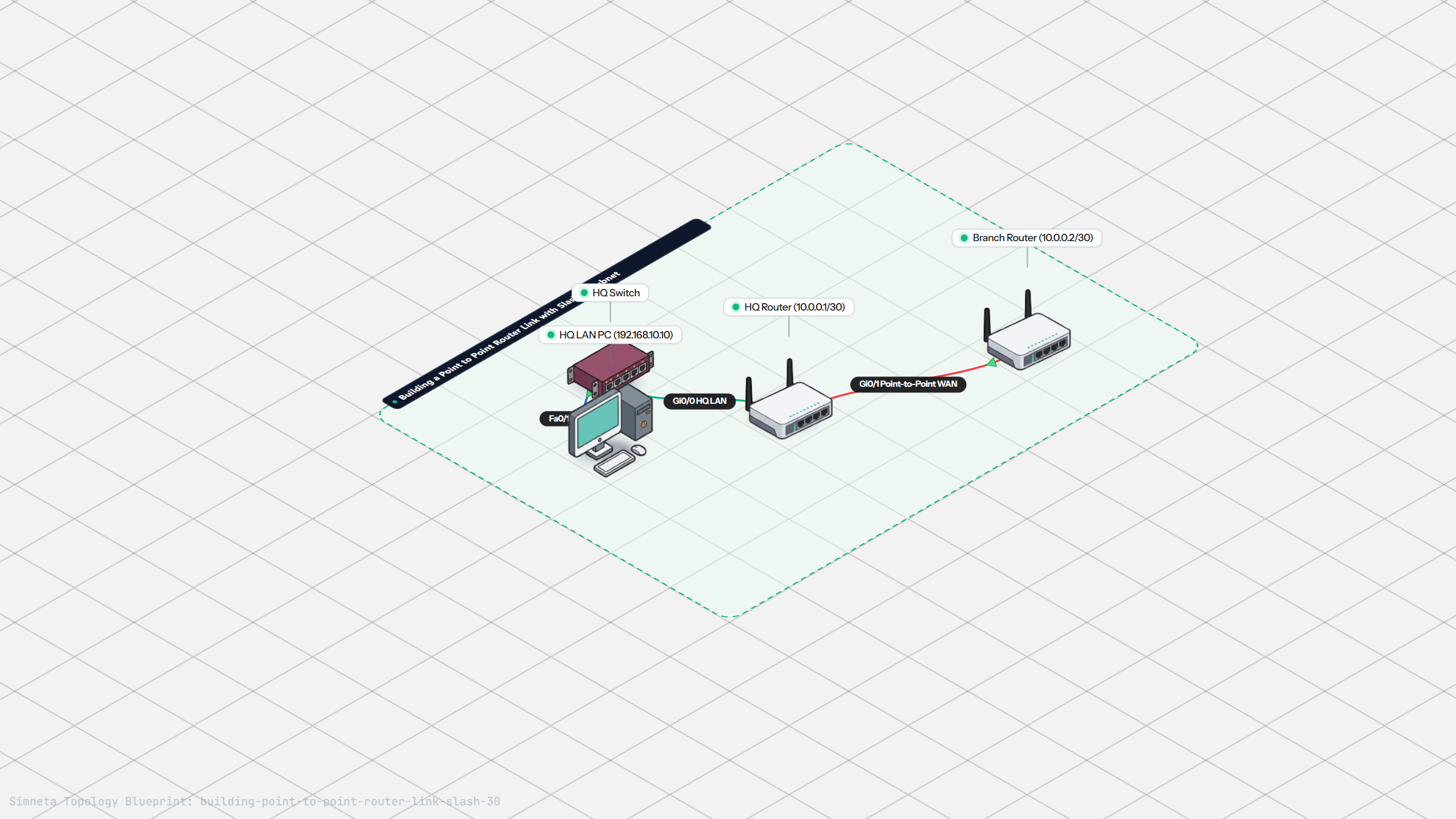
Connecting Routers with /30 Subnet
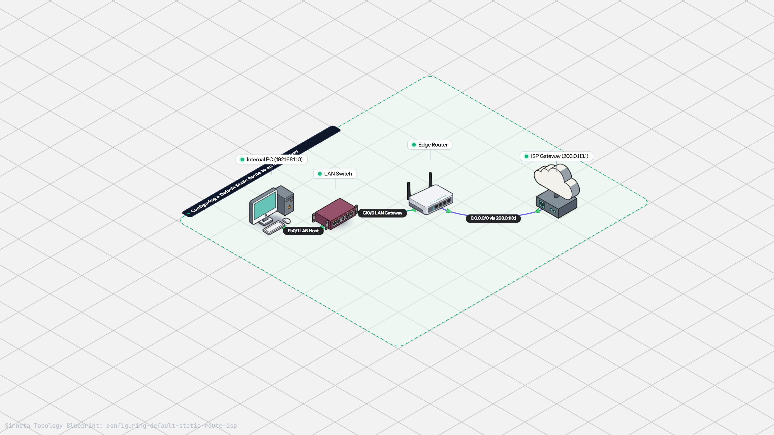
Configuring Default Static Route to ISP
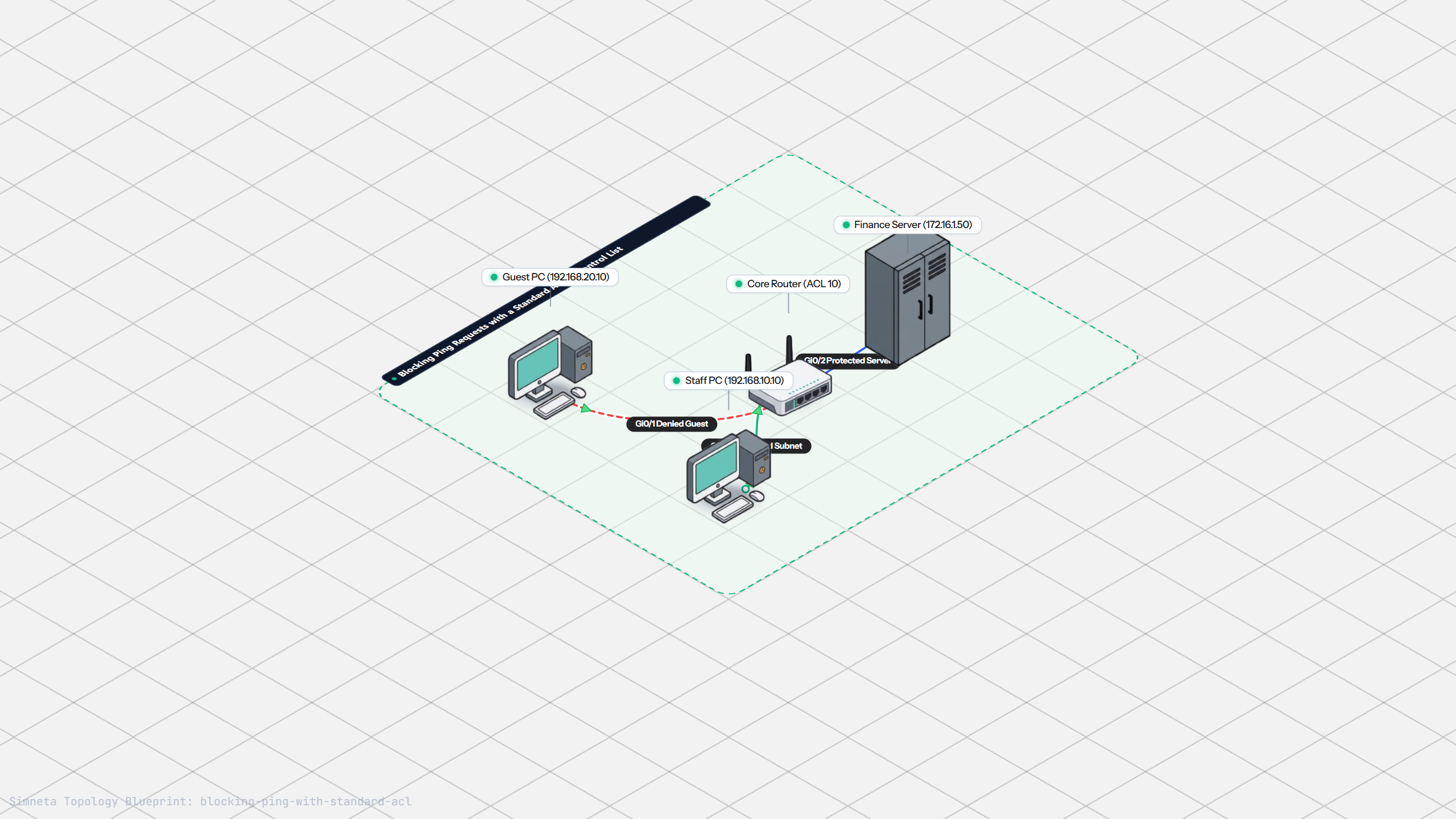
Blocking Ping with Standard ACL
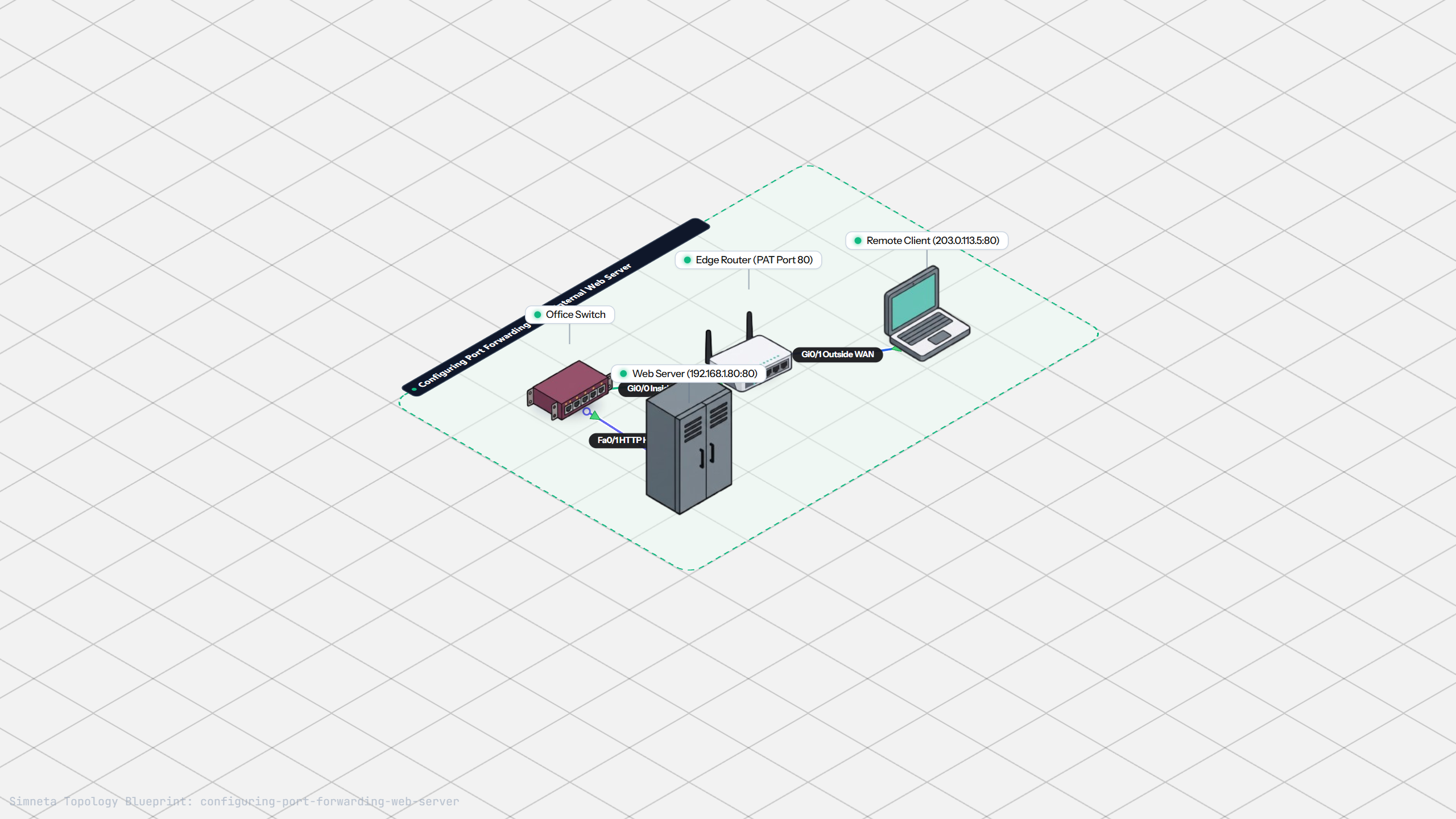
Port Forwarding for Web Servers
Fixing Default Gateway Misconfigurations
Discussion & Community Notes
Ask questions, share configuration tips, or discuss this laboratory topology.