
Fixing Default Gateway Misconfigurations
Master practical network troubleshooting techniques. Follow a structured diagnostic methodology to identify why a client computer can communicate locally on the office switch but fails to access external servers due to a faulty default gateway setting.
One of the most frequent tickets received by IT help desks is: "My computer can print to the office printer, but I cannot reach the internet or cloud email." To a novice, this seems baffling: if the network cable works and local files can be opened, why is the internet broken?
This symptom is the telltale signature of a Default Gateway Misconfiguration. When a client possesses a valid local IP address and subnet mask, local Layer 2 communication succeeds seamlessly. However, any packet destined for an outside IP requires the default gateway to exit the subnet. In this interactive troubleshooting lab, you will diagnose and repair this exact real-world scenario.
Systematic troubleshooting follows a logical isolation process rather than random guessing. By testing each layer of the OSI model in order—from physical link status to local subnet delivery, and finally upstream gateway routing—engineers isolate network failures within minutes.
Understanding the default gateway role gives you complete confidence when diagnosing client connectivity issues across corporate branch offices, hospital networks, and cloud hybrid environments.
You will learn how to use command-line diagnostic tools to inspect host network settings, trace Address Resolution Protocol failures for missing gateways, apply the configuration correction, and verify complete restoration of external network services.
Network Architecture Plan
| Segment | Interface | Subnet / Address | Functional Role |
|---|---|---|---|
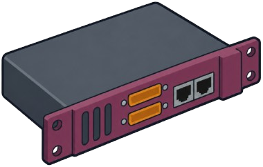
| Office Gateway Router | Gi0/0 | 192.168.1.1/24 | Legitimate Default Gateway |
| Office Switch | Fa0/1 - Fa0/3 | Layer 2 | Distribution Switch |
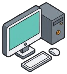
| Troubled Workstation | FastEthernet0 | 192.168.1.15/24 (Wrong GW) | Client with Connectivity Issue |
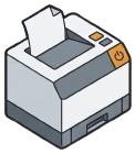
| Local Print Server | FastEthernet0 | 192.168.1.50/24 | Local Test Destination |
| External Cloud Server | Gi0/1 | 203.0.113.100/24 | Outside Test Destination |
Reproducing the Reported Symptom
A good troubleshooting investigation always begins by reproducing the exact issue reported by the user.
Open the terminal on the Troubled Workstation. First, ping the Local Print Server at 192.168.1.50. Notice that the ping returns 100% success. Next, attempt to ping the External Cloud Server at 203.0.113.100. Notice that all packets time out completely!
This split behavior provides our first crucial diagnostic clue: the local network infrastructure is healthy, but the exit path to outside networks is broken.
This approach demonstrates the classic Divide-and-Conquer Troubleshooting Model. By testing reachability at the boundary between your local switch and upstream routers, you split the potential problem space directly in half. You immediately avoid wasting time inspecting Ethernet patch cables, wall jacks, or local network card drivers.
Applying the OSI Layer Isolation Model:
192.168.1.0/24.When local ping succeeds but external ping fails, the physical cable, network card, and local switch are proven healthy. The root cause must reside in Layer 3 routing configuration.
Inspecting Host Network Parameters
Now inspect the network configuration of the workstation using ipconfig or show ip.
Carefully examine each field in the output. The IP address is 192.168.1.15, and the subnet mask is 255.255.255.0. But look closely at the Default Gateway value!
A single incorrect digit in the default gateway address prevents the host operating system from finding the router door to the outside world.
Parameter-by-Parameter Diagnostic Analysis:
IPv4 Address 192.168.1.15: Valid unique host address within the office range.Subnet Mask 255.255.255.0: Correct 24-bit subnet mask matching the office LAN.Default Gateway 192.168.1.254: Fault Discovered! According to the network topology plan, the legitimate office gateway router is configured as 192.168.1.1. The workstation was manually configured with 192.168.1.254, which does not exist on this network.route print (Windows) or netstat -rn (Linux), you will see that the operating system has bound its default quad-zero route (0.0.0.0/0) directly to gateway 192.168.1.254.Whenever an application requests an outside destination like 203.0.113.100, the workstation attempts to deliver the frame to 192.168.1.254, resulting in silent timeouts.
Common Admin Slip: Network engineers often debate whether routers should use the first usable address (.1) or the last usable address (.254). In environments where conventions differ across branch offices, technicians frequently configure .254 out of habit.
Testing Default Gateway Reachability
Confirm that the configured gateway address 192.168.1.254 is indeed dead by pinging it directly from the workstation.
The workstation broadcasts an ARP request for 192.168.1.254, but receives zero replies. Check the ARP table with arp -a to verify that no MAC binding exists for .254.
Understanding how ARP fails during gateway lookups reveals why external pings time out immediately.
Tracing the Failed Gateway Resolution:
192.168.1.254, the workstation checks its ARP cache. Finding no entry, it broadcasts: "Who has 192.168.1.254? Tell 192.168.1.15".192.168.1.1) receive the frame and ignore it because their IPs do not match .254.arp -a confirms that only the Print Server (192.168.1.50) exists in the table. The workstation cannot communicate with the outside world because it cannot find the physical hardware address of its exit gateway.Resolution Prerequisite: An operating system cannot transmit an IP packet across an Ethernet network until it resolves the destination or gateway MAC address. If ARP fails, the IP packet is discarded in local memory.
Applying the Gateway Correction
Now correct the configuration. Assign the proper IP settings to the workstation with the correct default gateway address 192.168.1.1.
Execute the static configuration command to update the operating system network stack.
Watch the terminal prompt as the operating system updates its internal routing table.
PC> ip 192.168.1.15 255.255.255.0 192.168.1.1
Checking for duplicate IP address...
Updating interface FastEthernet0:
  IP Address:      192.168.1.15
  Subnet Mask:     255.255.255.0
  Default Gateway: 192.168.1.1
Settings successfully updated.
Parameter-by-Parameter Command Breakdown:
ip: The client network configuration command utility.192.168.1.15: Preserves the workstation assigned host IP address.255.255.255.0: Maintains the correct 24-bit subnet mask.192.168.1.1: The corrected default gateway address pointing directly to interface GigabitEthernet0/0 of the office router.Network Destination: 0.0.0.0, Netmask: 0.0.0.0, Gateway: 192.168.1.1.Verification Rule: After modifying IP parameters, always run ipconfig once more before starting tests to confirm that typing mistakes did not introduce a new error.
Verifying Full End-to-End Restoration
Verify the fix in two stages. First, ping the legitimate gateway at 192.168.1.1. The router replies immediately in 1 ms.
Second, ping the External Cloud Server at 203.0.113.100. Packets now exit through the router and receive replies, fully restoring external connectivity!
Review the ping response metrics to confirm complete circuit health.
Analyzing the Successful Restoration:
time=1ms TTL=255 confirms that the workstation resolved the router real MAC address and established bidirectional communication with the local gateway.time=12ms TTL=63 proves that the workstation forwarded the frame to the gateway, the gateway routed the packet across its WAN interface to the cloud server, and the reply returned safely.With 0% packet loss to both local and cloud endpoints, the troubleshooting ticket can be officially closed.
Documentation Best Practice: When resolving gateway misconfigurations, always document the root cause in the ticketing system and verify whether DHCP options should be updated to prevent recurring manual errors.
Related Network Labs
Continue your network simulation practice with these recommended labs.
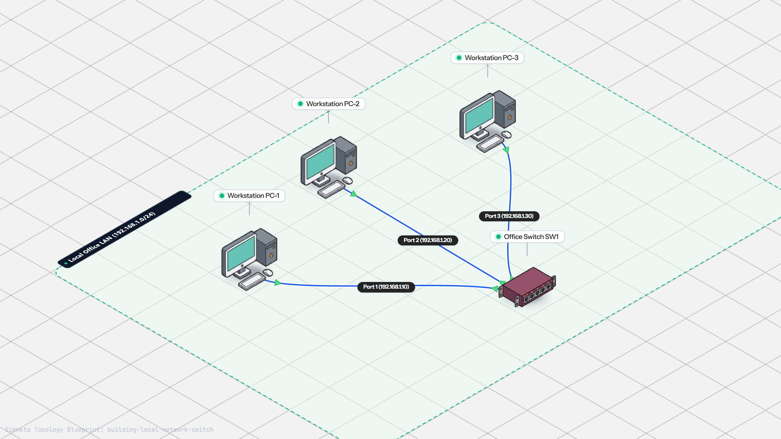
Building a Local Office LAN with a Switch
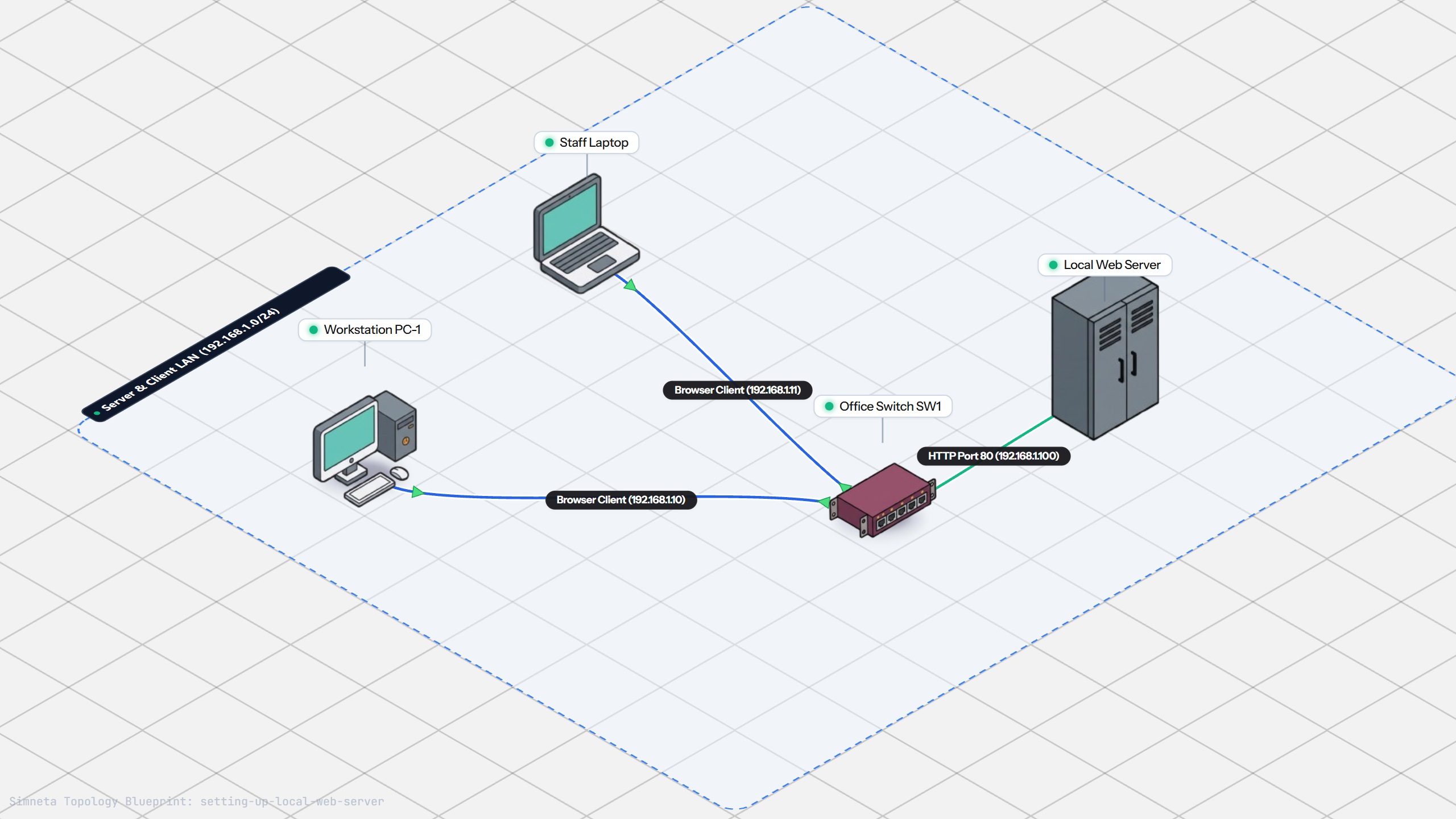
Setting Up a Local Web Server
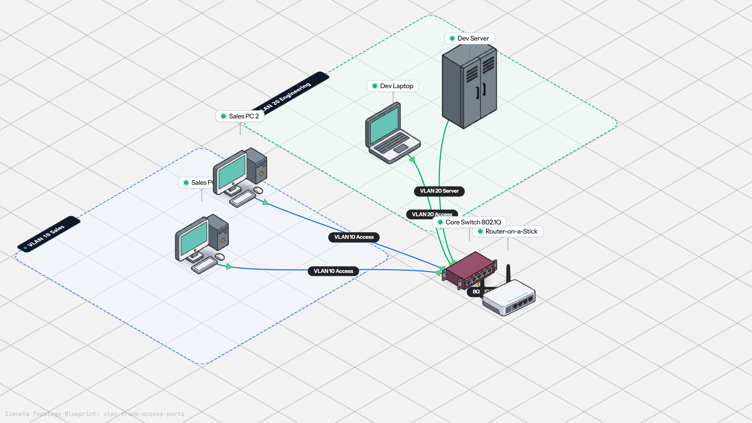
VLAN Trunking with 802.1Q
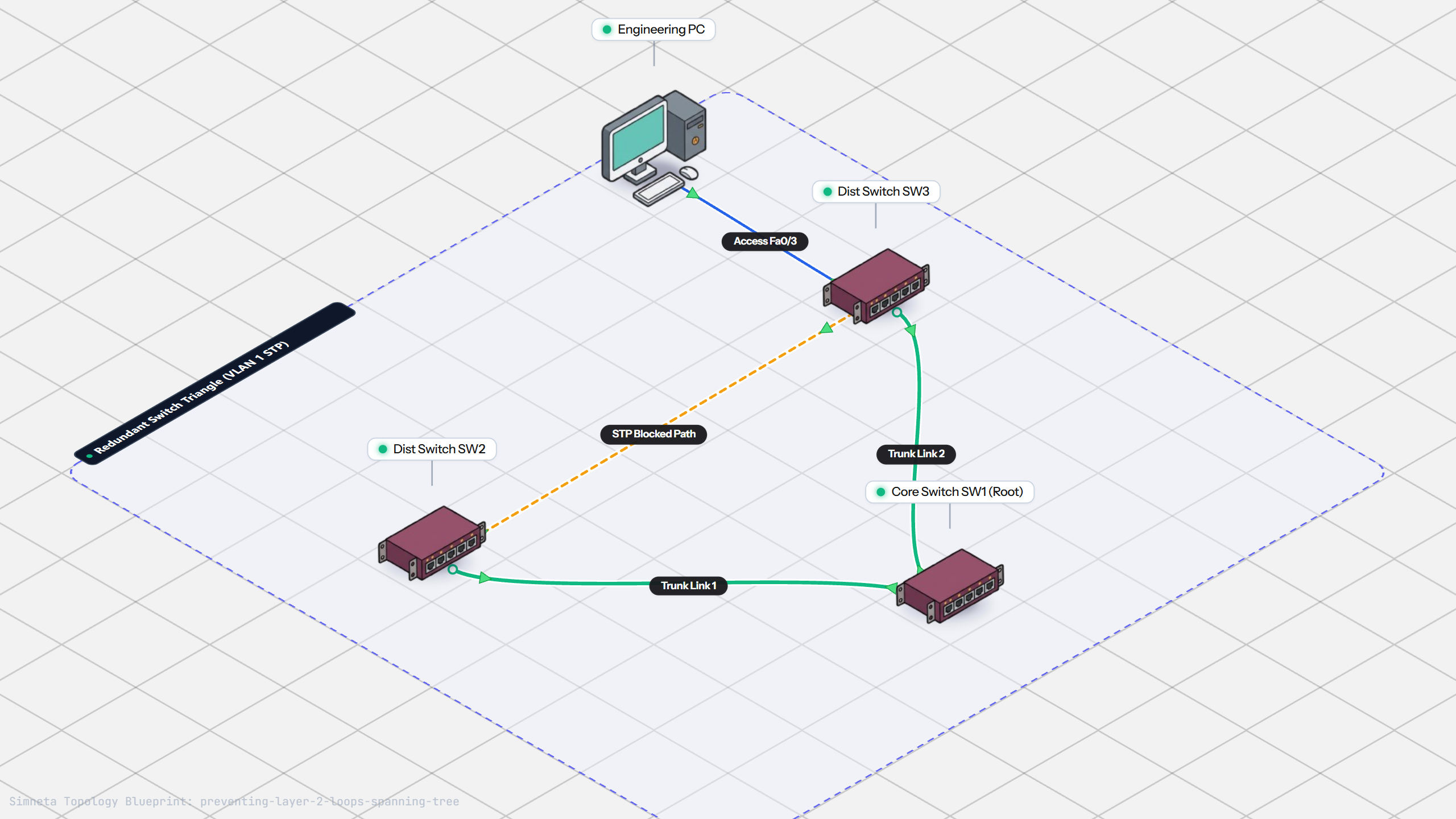
Preventing Loops with Spanning Tree
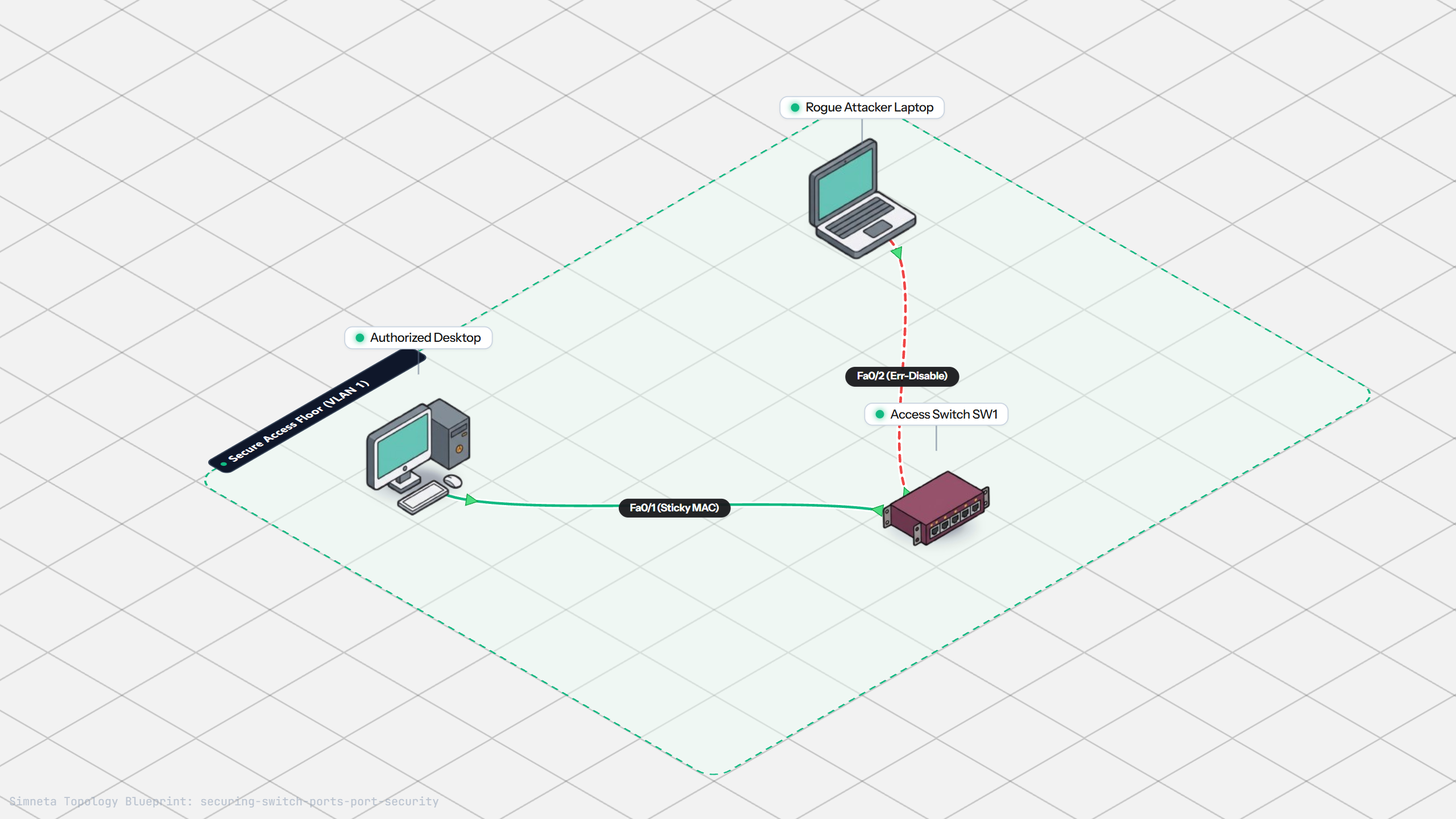
Securing Switch Ports with Port Security
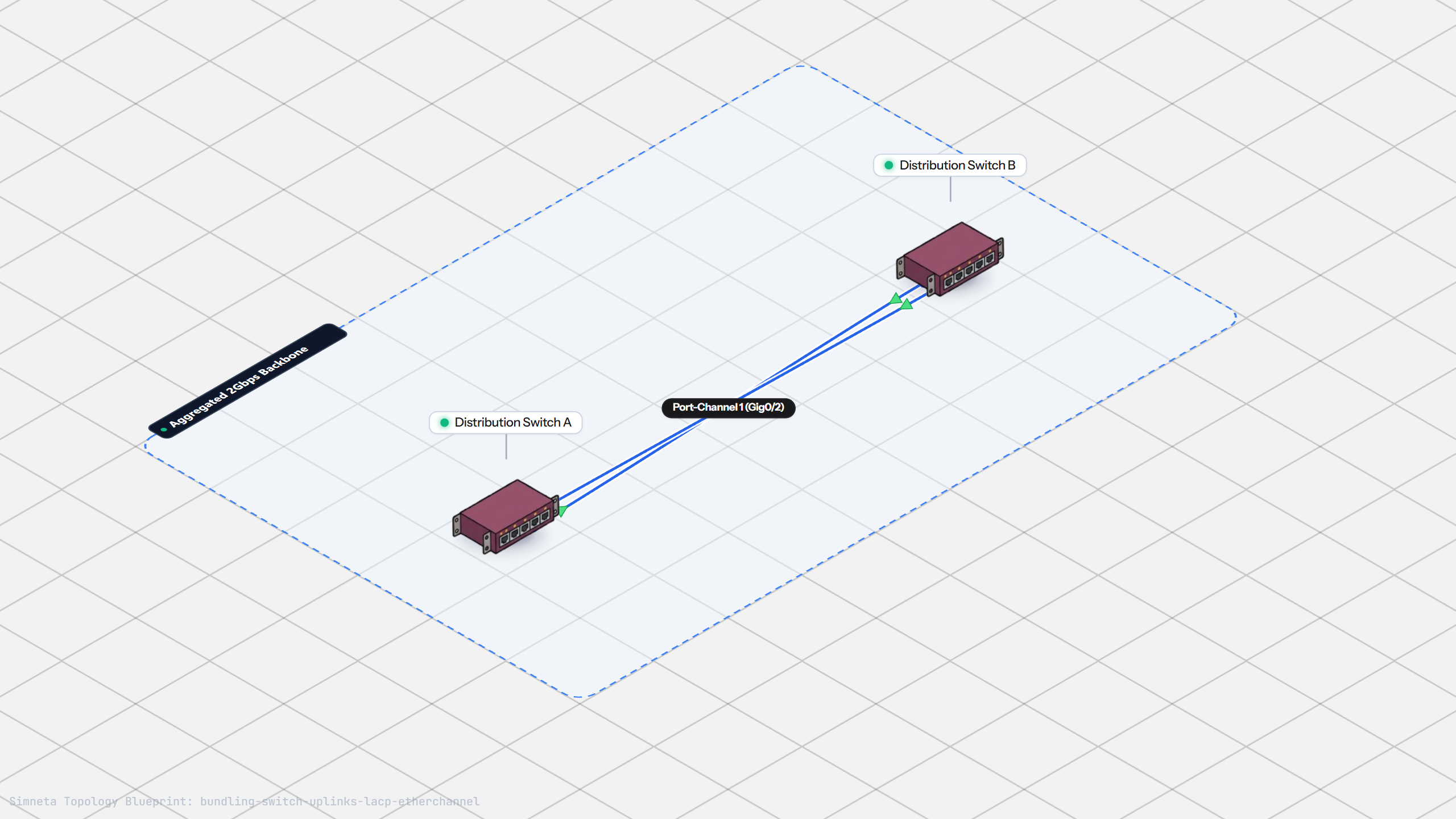
Bundling Switch Uplinks with LACP EtherChannel
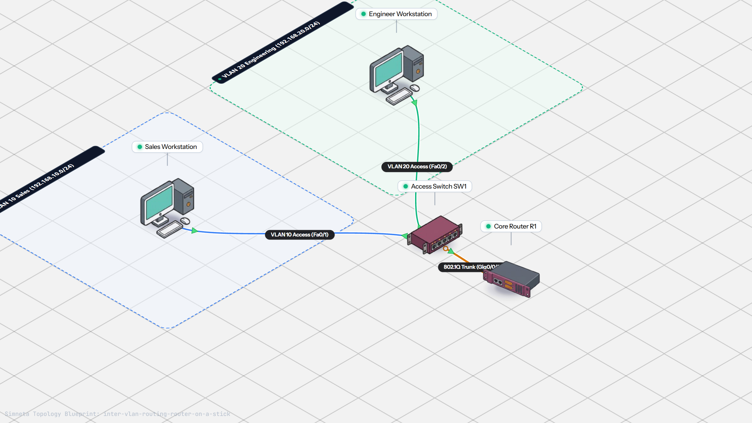
Inter-VLAN Routing with Router-on-a-Stick
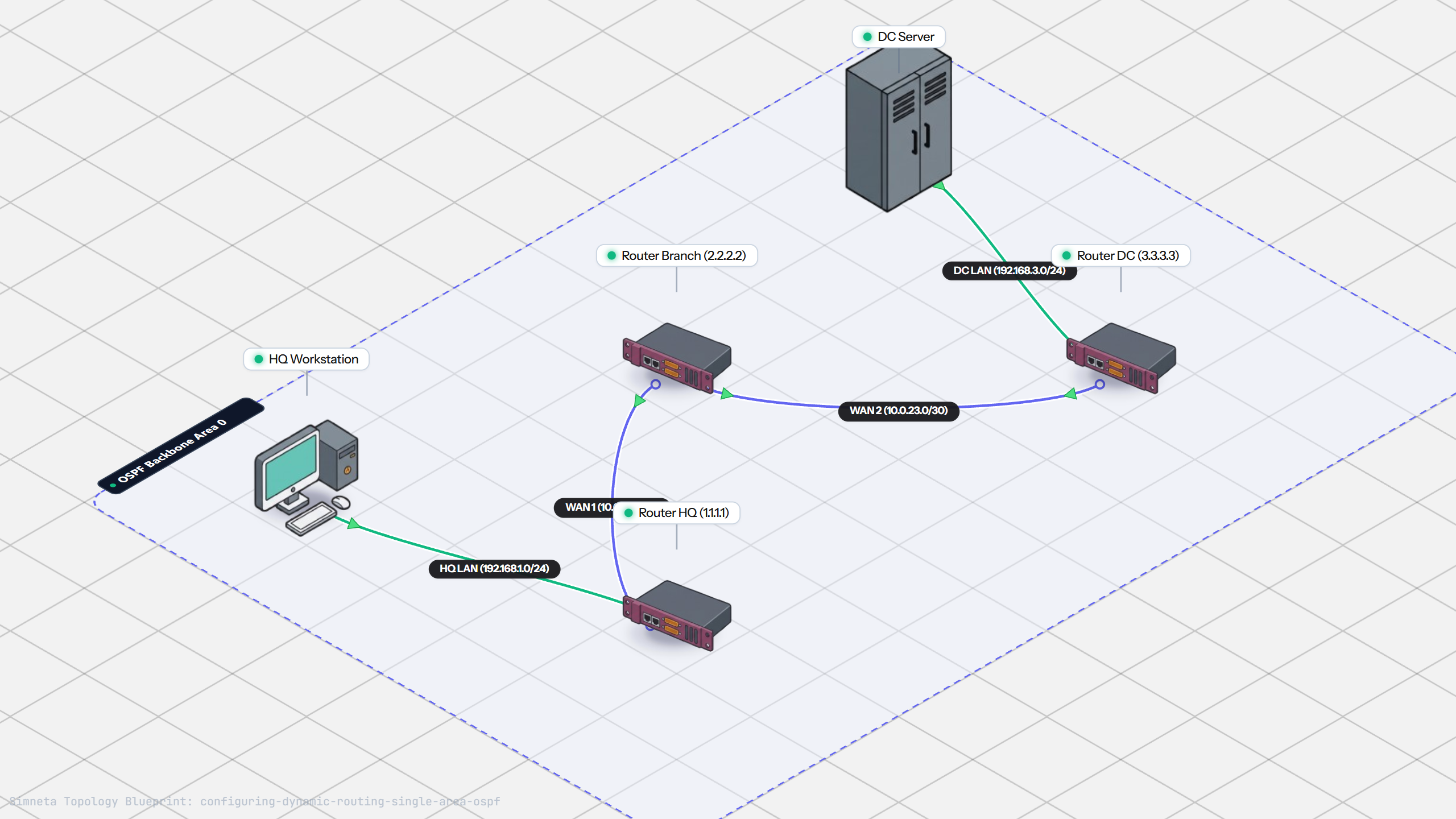
Dynamic Routing with Single-Area OSPF
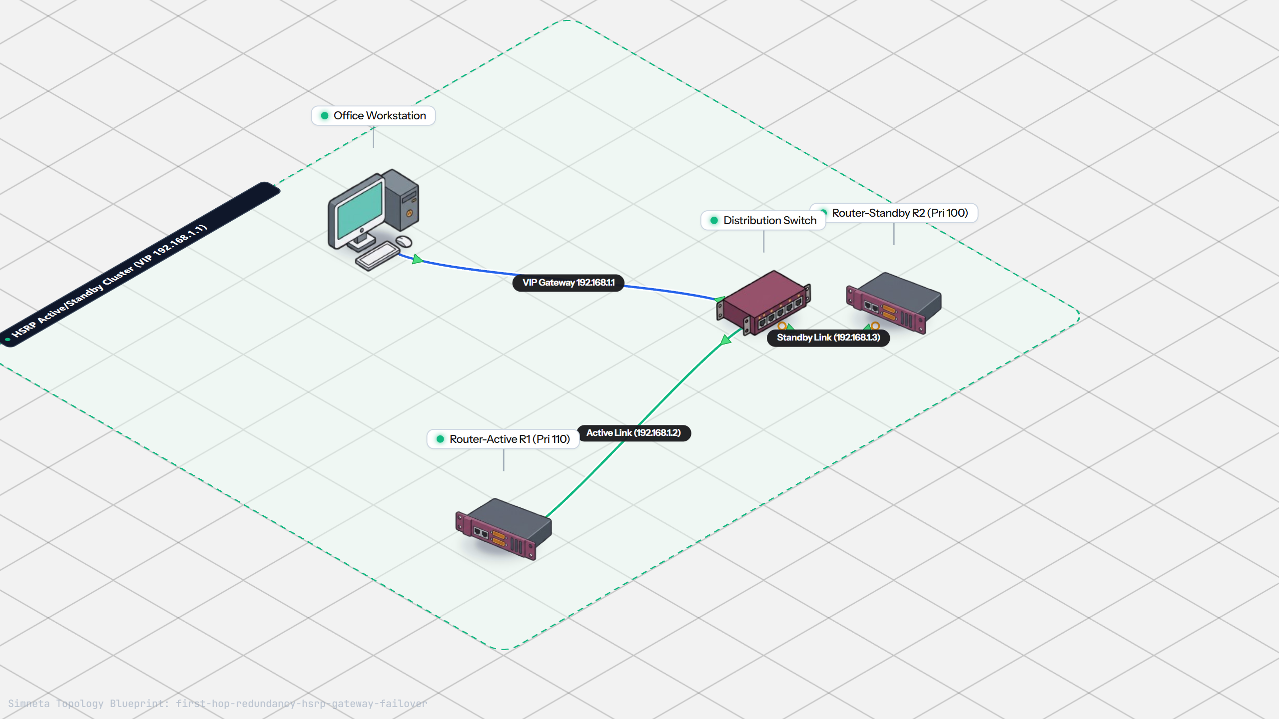
Gateway Redundancy with HSRP Failover
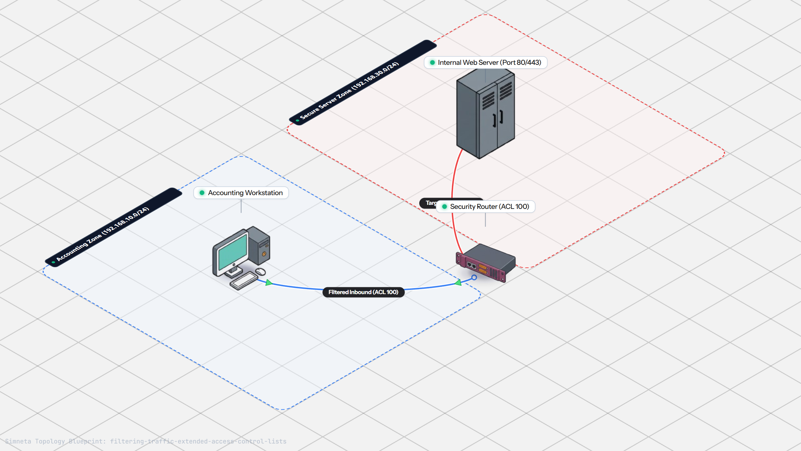
Filtering Traffic with Extended ACLs
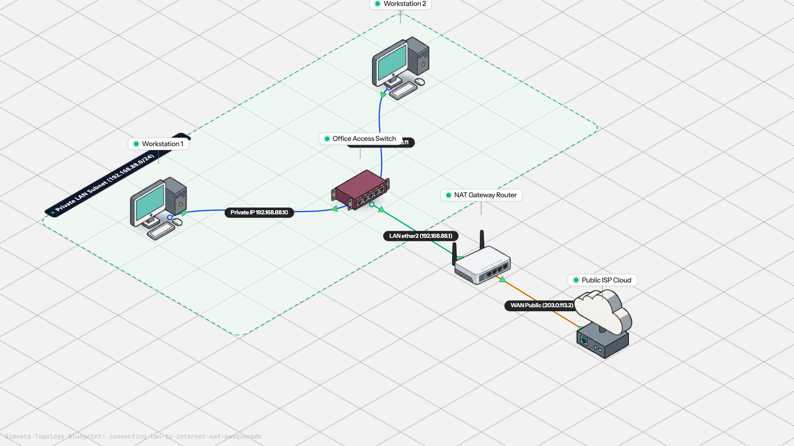
Connecting LAN to Internet with NAT
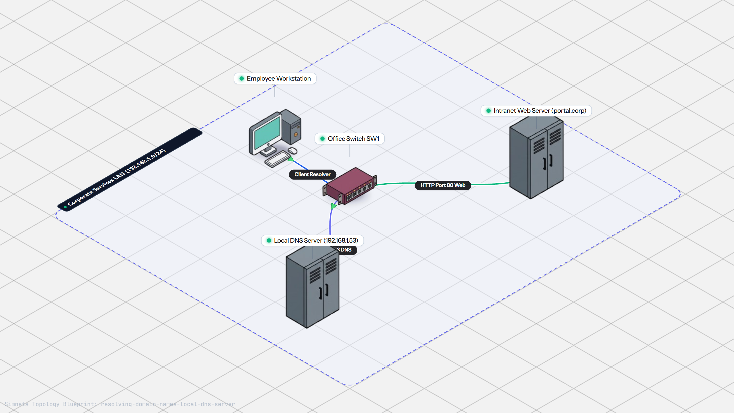
Resolving Domain Names with Local DNS
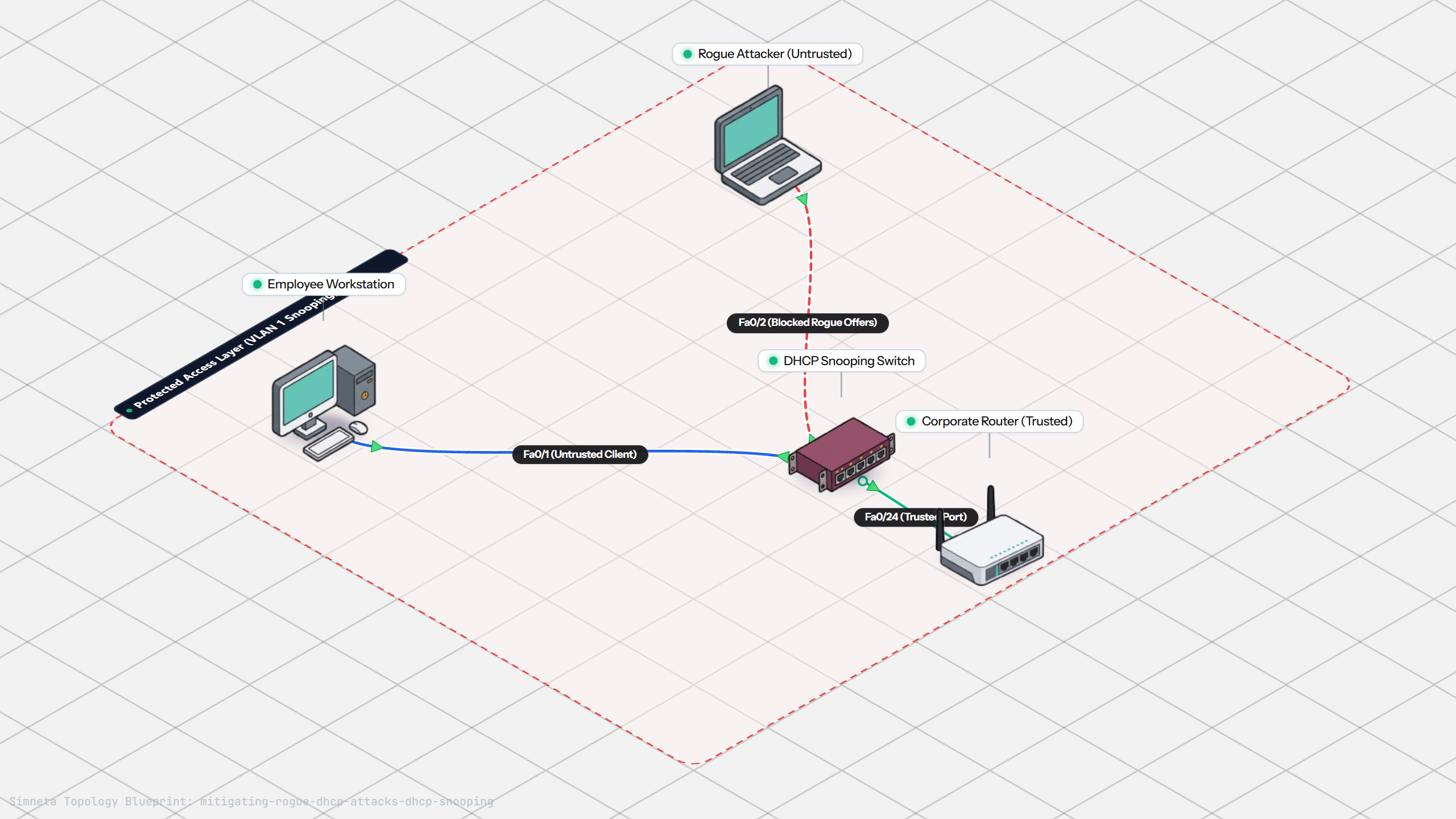
Stopping Rogue DHCP with Snooping
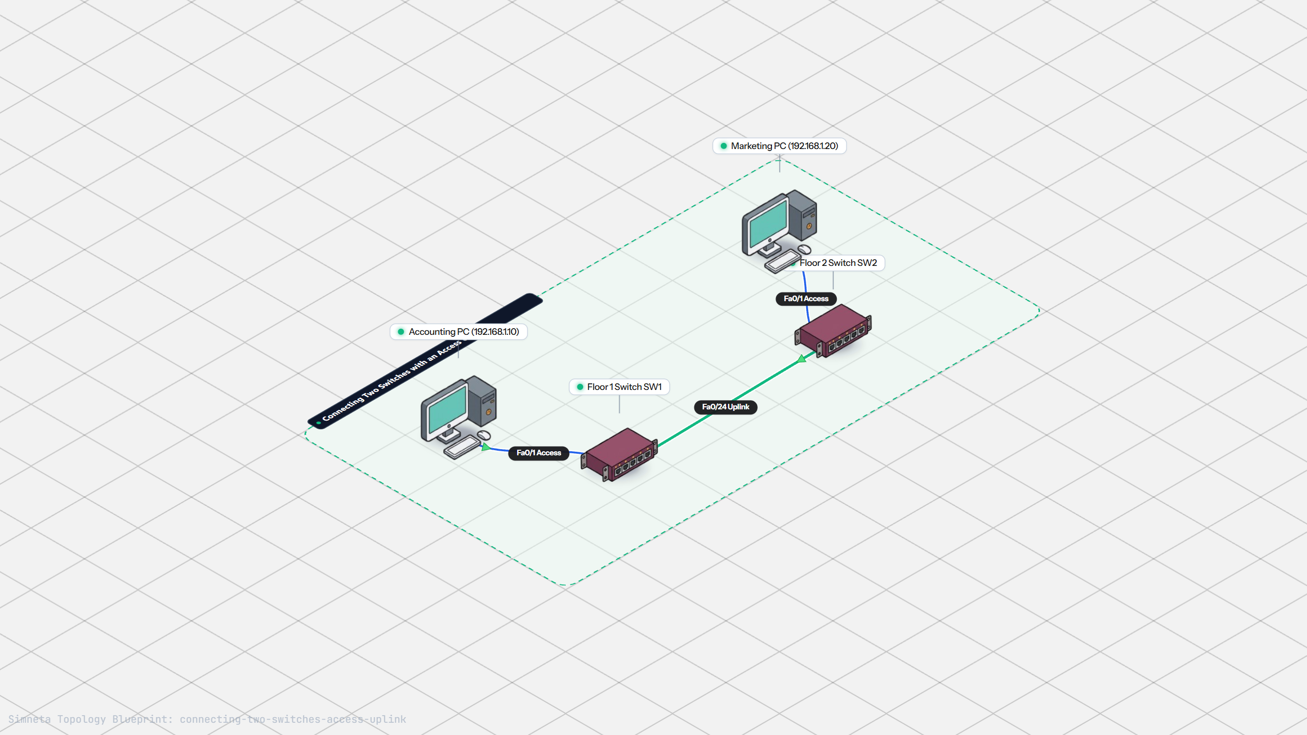
Connecting Two Switches with an Access Uplink
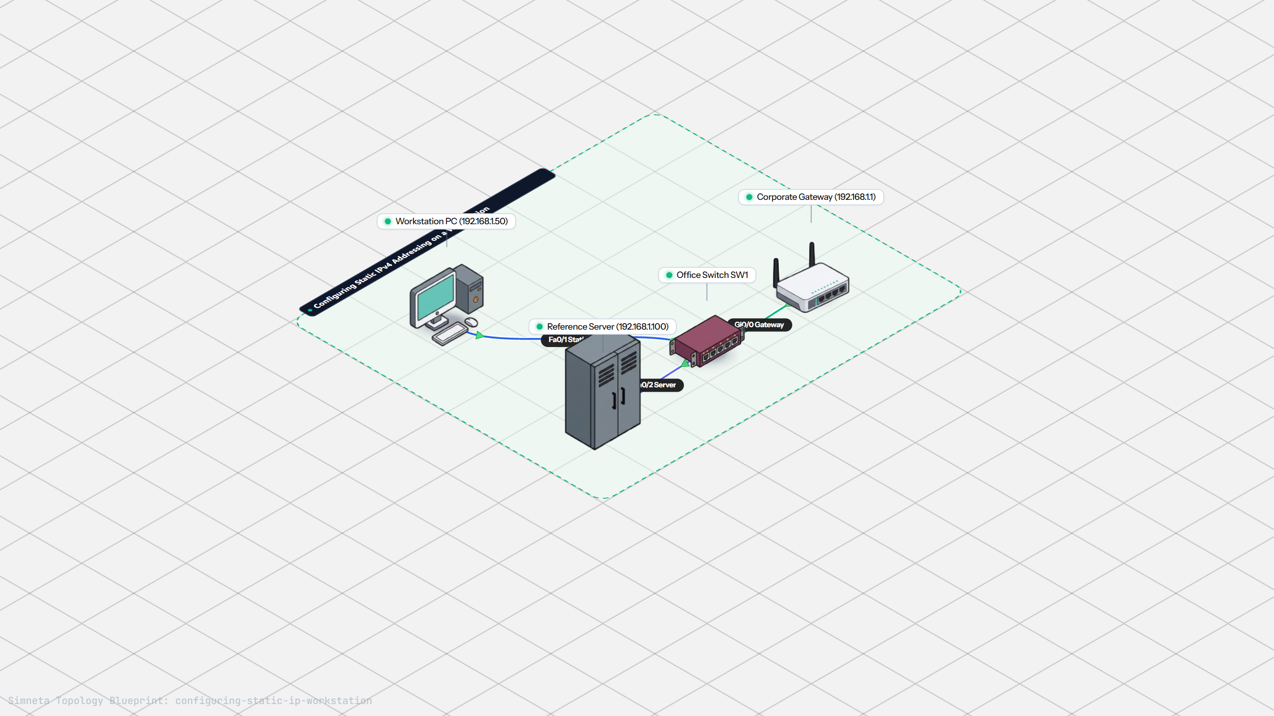
Configuring Static IP on Workstation
Testing Reachability and Latency with Ping
Inspecting ARP Cache Tables
Setting Up DHCP Static Reservations
Connecting Routers with /30 Subnet
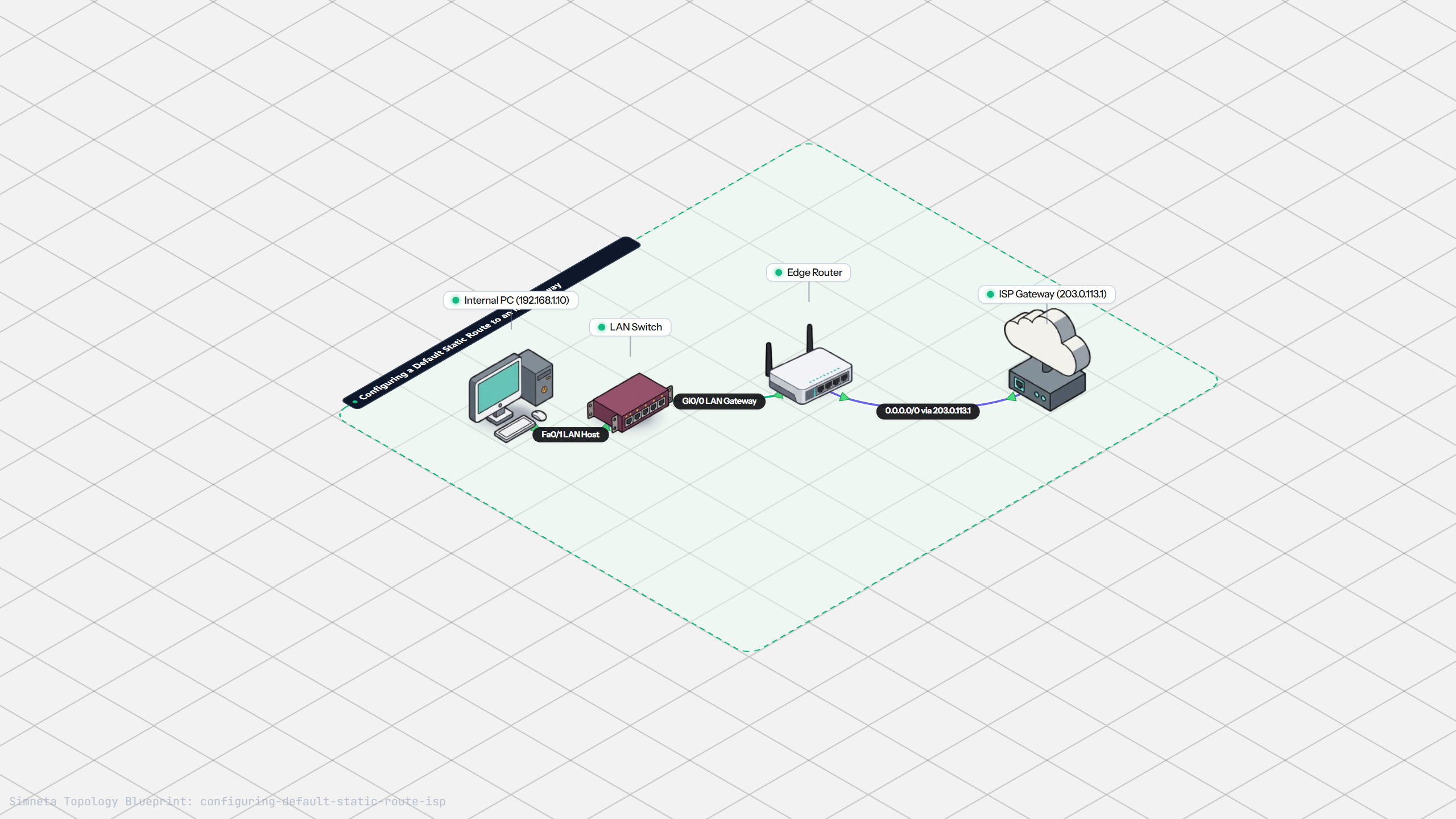
Configuring Default Static Route to ISP
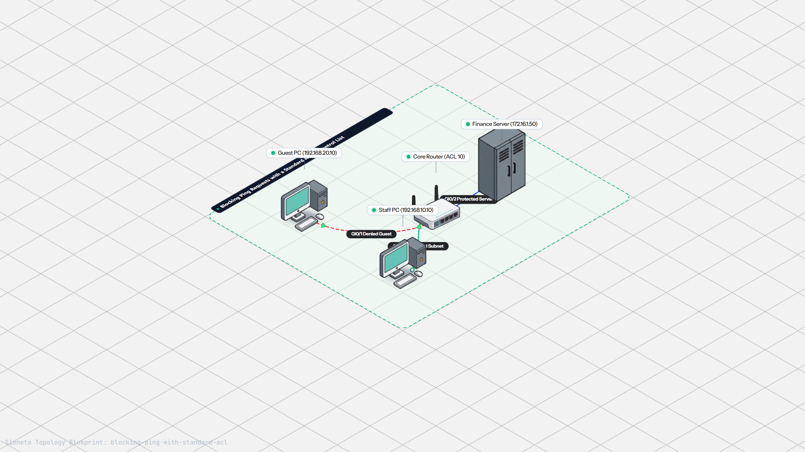
Blocking Ping with Standard ACL
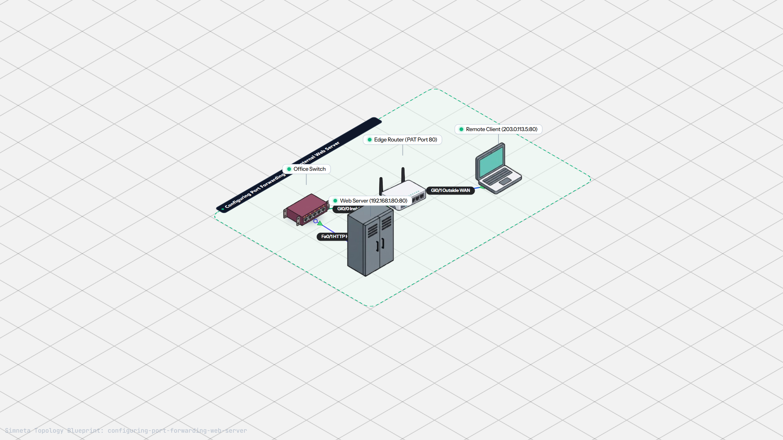
Port Forwarding for Web Servers
Discussion & Community Notes
Ask questions, share configuration tips, or discuss this laboratory topology.