
Connecting Routers with /30 Subnet
Conserve valuable IPv4 address space across wide area network links. Learn how a 30-bit subnet mask provides exactly two usable host addresses, configure router interconnect interfaces, and test point-to-point IP connectivity.
When connecting two routers across a dedicated WAN link or inter-building fiber cable, there are only ever two devices on that wire: the router at site A and the router at site B. If an engineer assigns a standard /24 subnet (which provides 254 usable addresses) to this link, 252 IP addresses are permanently wasted.
To maximize address efficiency, network architects use a /30 Subnet Mask (255.255.255.252). A /30 subnet contains only 4 total addresses: 1 network ID, 1 broadcast address, and exactly 2 usable host addresses. In this hands-on tutorial, you will configure a /30 point-to-point link between a Headquarters router and a Branch router.
In modern enterprise network engineering, address conservation is critical. While modern routers support RFC 3021 (/31 subnets for point-to-point links), the classic /30 prefix remains the universal industry standard for WAN circuits, carrier Ethernet interconnects, and inter-router transport links across all vendor platforms.
By configuring point-to-point subnets manually, you will understand how routing tables register connected networks and host routes, and observe how routers exchange direct ICMP traffic across dedicated physical links.
Network Architecture Plan
| Segment | Interface | Subnet / Address | Functional Role |
|---|---|---|---|
| HQ Router | GigabitEthernet0/1 | 10.0.0.1/30 (Mask 255.255.255.252) | Headquarters WAN Gateway |
| Branch Router | GigabitEthernet0/1 | 10.0.0.2/30 (Mask 255.255.255.252) | Branch Office WAN Gateway |
| WAN Fiber Cable | HQ Gi0/1 to Branch Gi0/1 | 10.0.0.0/30 Subnet Block | Point to Point Interconnect |
| HQ LAN PC | FastEthernet0 | 192.168.10.10/24 | HQ Local Host |
The 30-Bit Subnet Mask
An IPv4 address consists of 32 bits. A /30 mask leaves only 2 bits for host addressing. Using the binary formula 2^H - 2, we calculate 2^2 - 2 = 2 usable host addresses.
For the network block 10.0.0.0/30, the address breakdown is mathematically rigid:
10.0.0.0 is the Network Address (cannot be assigned to hosts)10.0.0.1 is the First Usable Host Address (assigned to Router 1)10.0.0.2 is the Second Usable Host Address (assigned to Router 2)10.0.0.3 is the Broadcast Address (cannot be assigned to hosts)Because there are only two usable IP addresses, it is impossible for a third device to join this network segment. This tight boundary guarantees that WAN links remain isolated point-to-point channels.
Additionally, dynamic routing protocols like Open Shortest Path First (OSPF) recognize /30 networks as point-to-point network types. When OSPF runs on a point-to-point link, it skips the Designated Router (DR) and Backup Designated Router (BDR) election process entirely. This streamlined protocol behavior forms routing adjacencies in seconds and minimizes protocol chatter across wide area links.
Subnet Mask:     255.255.255.252
Binary Octets:   11111111.11111111.11111111.11111100
Network Bits:    30 consecutive ones (Prefix /30)
Host Bits:       2 remaining zeros (2^2 = 4 total addresses)
Usable Formula:  2^H - 2 = 2^2 - 2 = 2 usable hosts
Understanding the 2-Bit Host Field:
10.0.0.0). This is reserved as the network identifier and represents the entire wire.10.0.0.1). This is assigned to the first router interface.10.0.0.2). This is assigned to the opposite router interface.10.0.0.3). This is reserved as the directed broadcast address for the subnet.This mathematical structure ensures that no IP addresses are wasted when connecting two dedicated routing devices together.
In binary, the mask 255.255.255.252 ends with 11111100. The last two zeros allow only binary combinations 01 and 10 for active host interfaces.
Configuring the Headquarters Router
Open the console on the Headquarters Router. Enter global configuration mode and navigate to interface GigabitEthernet0/1.
Assign the first usable IP address 10.0.0.1 with subnet mask 255.255.255.252, and execute no shutdown to power on the interface hardware.
Always assign a descriptive port label so field engineers can quickly identify link endpoints during maintenance or circuit testing.
HQ-Router# configure terminal
HQ-Router(config)# interface GigabitEthernet0/1
HQ-Router(config-if)# description WAN-P2P-Link-to-Branch
HQ-Router(config-if)# ip address 10.0.0.1 255.255.255.252
HQ-Router(config-if)# no shutdown
HQ-Router(config-if)# exit
Parameter-by-Parameter Command Breakdown:
interface GigabitEthernet0/1: Enters interface configuration mode for the physical gigabit port connecting to the WAN cable.description WAN-P2P-Link-to-Branch: Documents the purpose of the port in the running configuration, visible in diagnostic outputs.ip address 10.0.0.1 255.255.255.252: Binds the first usable host IP and 30-bit subnet mask to this physical port.no shutdown: Changes the administrative state from administratively down to up. On Cisco routers, physical interfaces are turned off by default for security.Administrative State: Unlike switches whose ports are active by default, router interfaces remain administratively down until you explicitly issue the no shutdown command.
Configuring the Branch Router
Now open the console on the Branch Office Router. Configure its matching interconnect port GigabitEthernet0/1 with the second usable address 10.0.0.2 and identical mask 255.255.255.252.
Issue no shutdown. As soon as both sides are administrative UP, the physical carrier signals and line protocol states transition to UP/UP.
Notice that both routers must agree on the exact same subnet mask. If one side uses /30 and the other uses /24, link routing protocols like OSPF will reject neighbor relationships.
Branch-Router# configure terminal
Branch-Router(config)# interface GigabitEthernet0/1
Branch-Router(config-if)# description WAN-P2P-Link-to-HQ
Branch-Router(config-if)# ip address 10.0.0.2 255.255.255.252
Branch-Router(config-if)# no shutdown
Branch-Router(config-if)# exit
Parameter-by-Parameter Command Breakdown:
ip address 10.0.0.2 255.255.255.252: Assigns the second (and final) usable host address in the 10.0.0.0/30 block.no shutdown: Completes the circuit activation. The physical link pulses activate the line protocol.%LINK-3-UPDOWN: Interface GigabitEthernet0/1, changed state to up and %LINEPROTO-5-UPDOWN: Line protocol on Interface GigabitEthernet0/1, changed state to up.This dual-message sequence confirms that electrical signals (Layer 1) and data link framing (Layer 2) are fully functional.
Subnet Boundary Enforcement: If you attempt to assign 10.0.0.3 to this port, Cisco IOS will reject the command with the error: Bad mask /30 for address 10.0.0.3 because .3 is the broadcast address.
Verifying Interface Carrier Status
Execute the command show ip interface brief on the Headquarters Router to verify link status.
Next, check the routing table with show ip route. Notice that the router automatically installs a C (Connected) route for 10.0.0.0/30 and an L (Local) host route for 10.0.0.1/32.
Understanding the difference between Connected and Local routes is essential for diagnosing modern router behavior.
Status and Route Breakdown:
Status up / Protocol up: The first up confirms physical electrical carrier signals. The second up confirms Layer 2 data link framing and keepalive exchanges.C - 10.0.0.0/30: A directly connected network route. Any packet destined for 10.0.0.2 will be forwarded out of GigabitEthernet0/1 using direct Layer 2 framing.L - 10.0.0.1/32: A local host route introduced in Cisco IOS 15. The /32 mask represents the router own interface address, allowing the router processor to handle traffic destined specifically for itself with maximum efficiency.Two-State Rule: If Status is up but Protocol is down, check for Layer 2 protocol mismatches, clock rate errors on serial cables, or keepalive failures.
Testing Point-to-Point Reachability
From the Headquarters Router prompt, ping the neighbor Branch Router interface at 10.0.0.2.
Observe five exclamation marks (!!!!!) indicating a 100% success rate with sub-millisecond round-trip response times.
Testing with ping verifies that both routers can encapsulate IP packets into Ethernet frames and process responses in real time.
Analyzing Cisco IOS Ping Output:
Exclamation Mark (!): Each exclamation mark represents one successful ICMP Echo Reply received within the 2-second timeout window.Period (.): A period indicates a request that timed out without receiving a reply.U: Indicates that an intermediate router replied with an ICMP Destination Unreachable message.Round-trip min/avg/max = 1/1/2 ms: On a direct point-to-point fiber or patch link, response times are almost instantaneous because there are zero intermediate switches or routing hops between the two interfaces.Packet Size Default: Notice that Cisco IOS pings send 100-byte ICMP packets by default, whereas Windows workstations send 32-byte packets. You can test jumbo frames using the command ping 10.0.0.2 size 1500.
Related Network Labs
Continue your network simulation practice with these recommended labs.
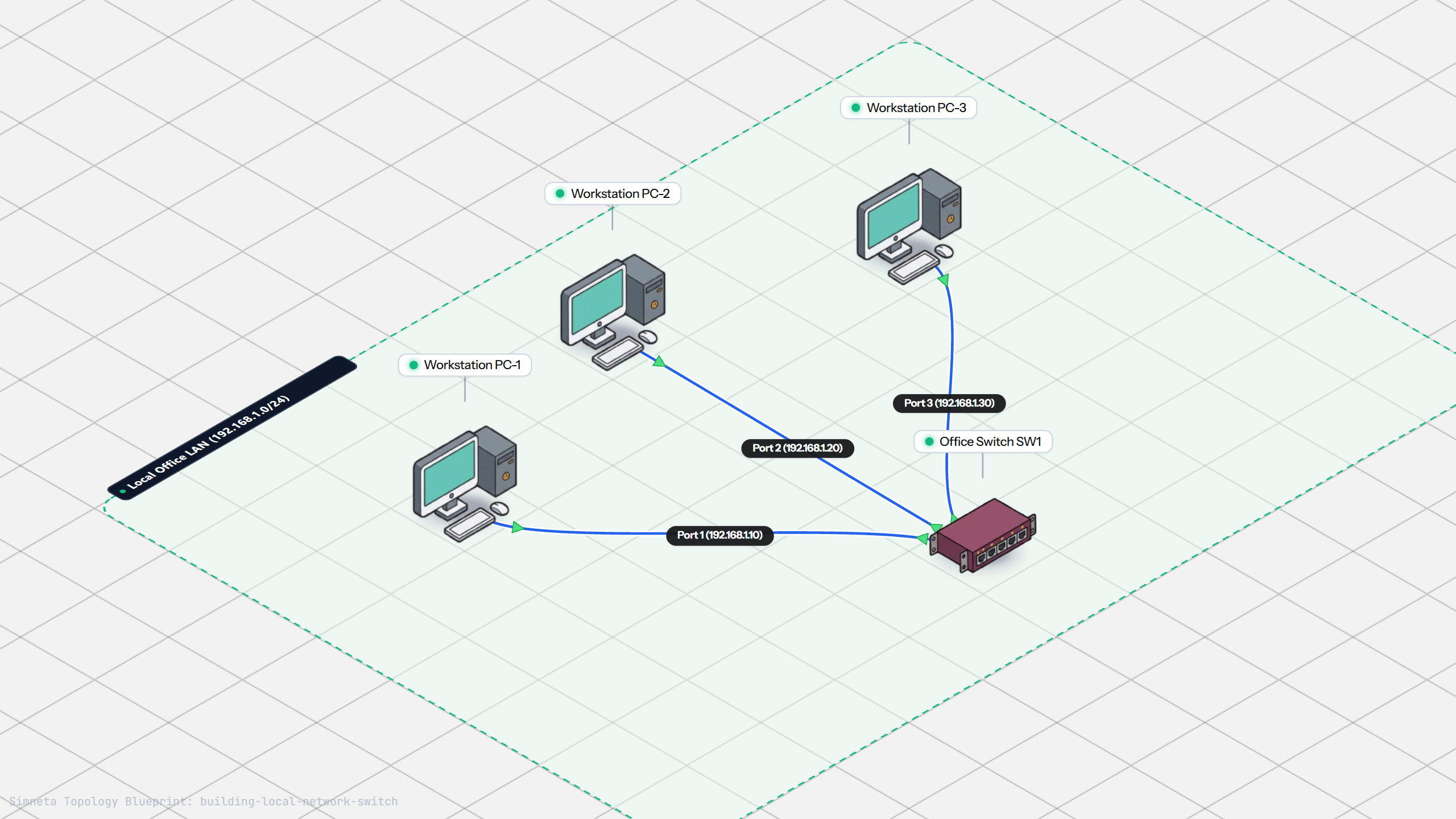
Building a Local Office LAN with a Switch
Setting Up a Local Web Server
VLAN Trunking with 802.1Q
Preventing Loops with Spanning Tree
Securing Switch Ports with Port Security
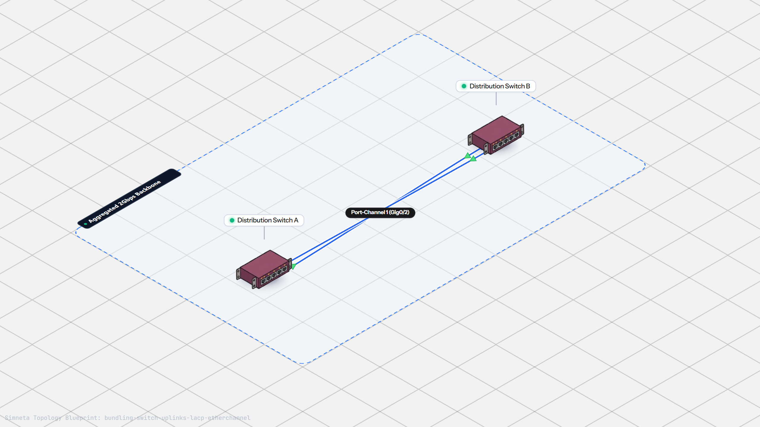
Bundling Switch Uplinks with LACP EtherChannel
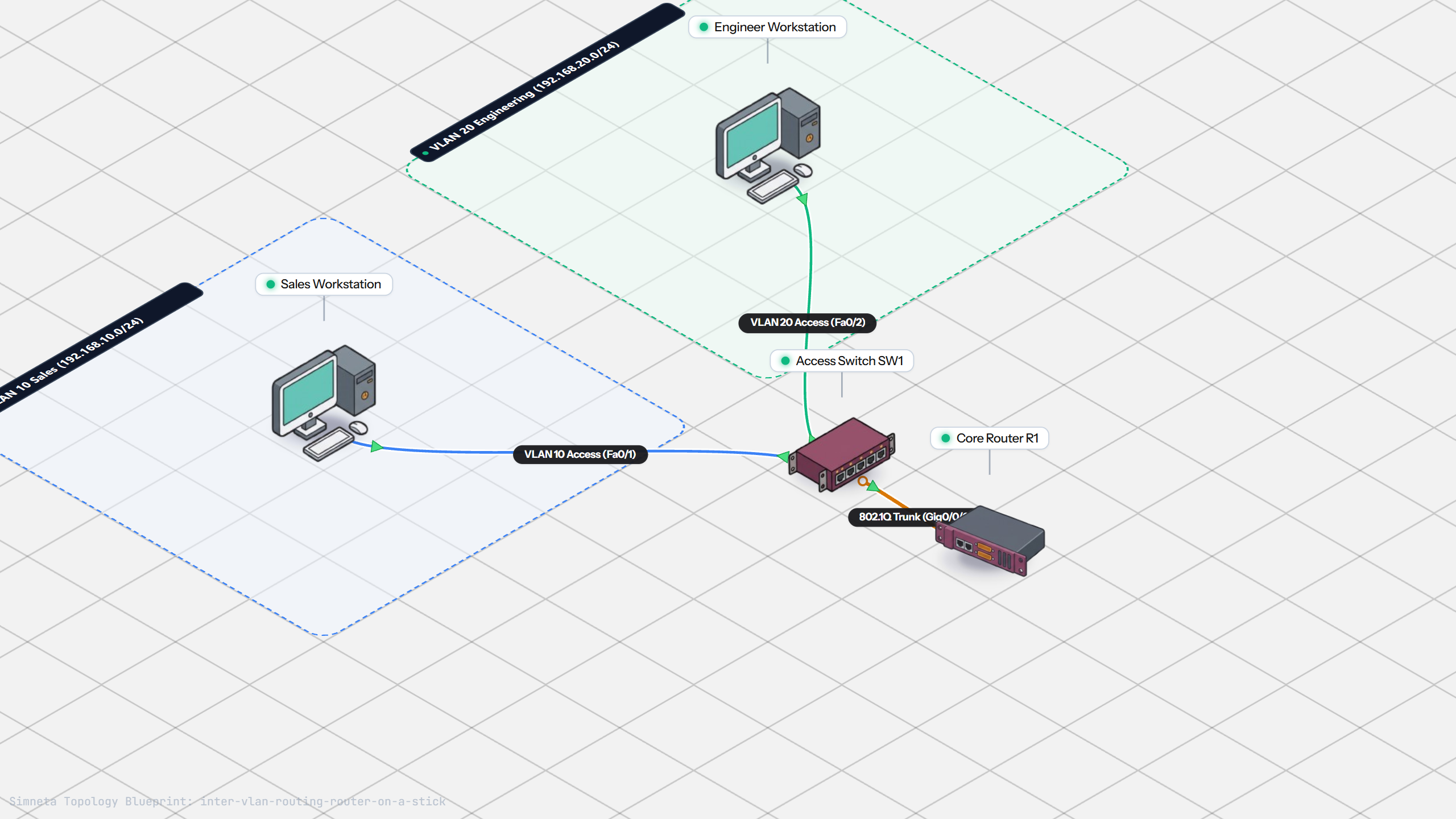
Inter-VLAN Routing with Router-on-a-Stick
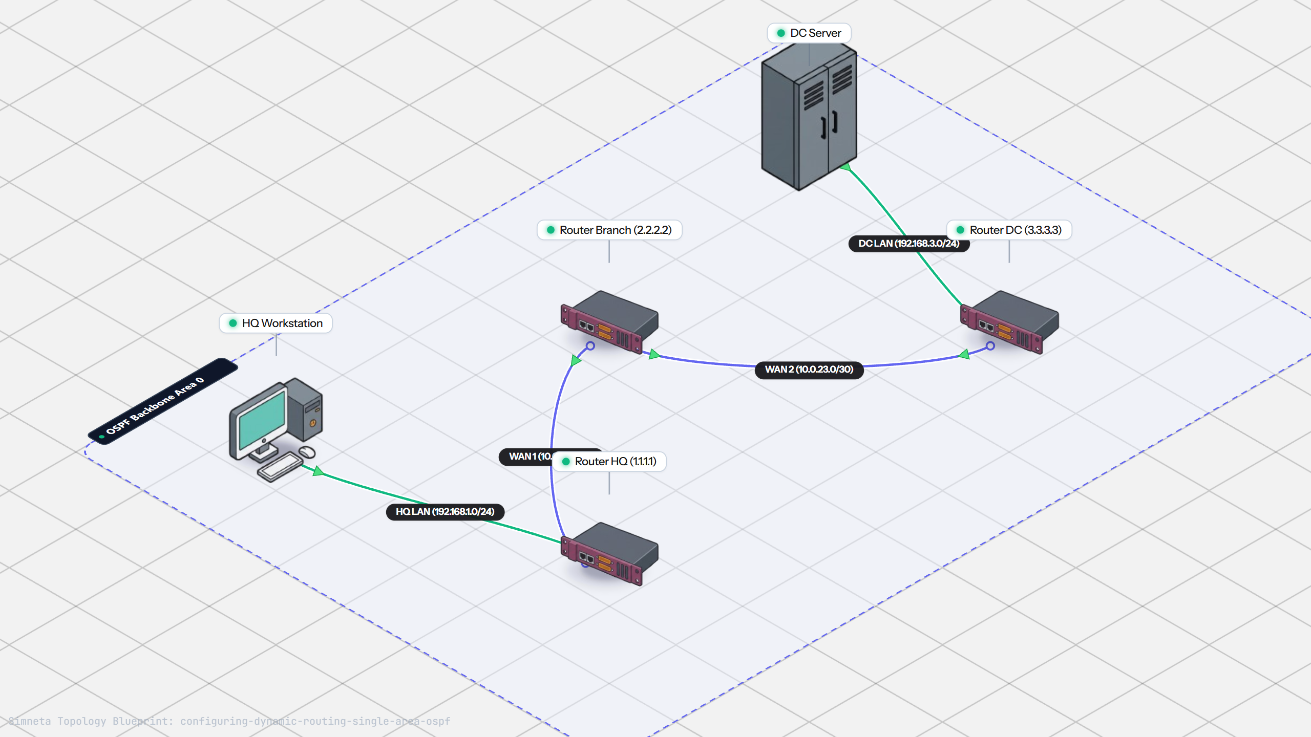
Dynamic Routing with Single-Area OSPF
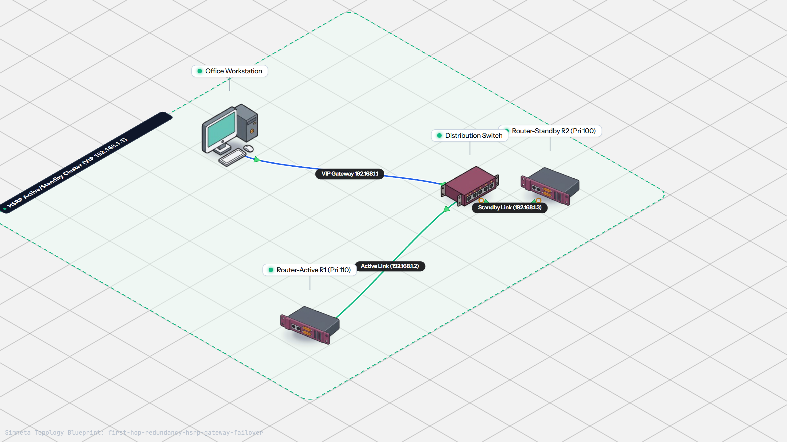
Gateway Redundancy with HSRP Failover
Filtering Traffic with Extended ACLs
Connecting LAN to Internet with NAT
Resolving Domain Names with Local DNS
Stopping Rogue DHCP with Snooping
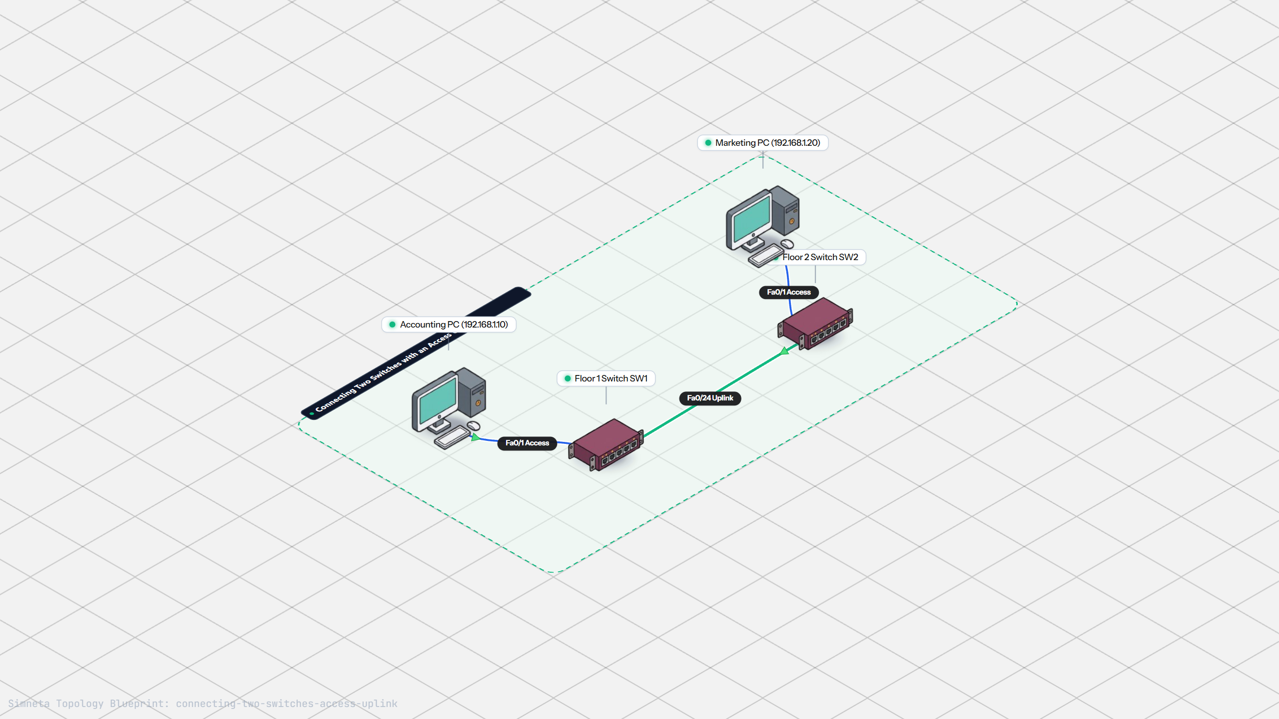
Connecting Two Switches with an Access Uplink
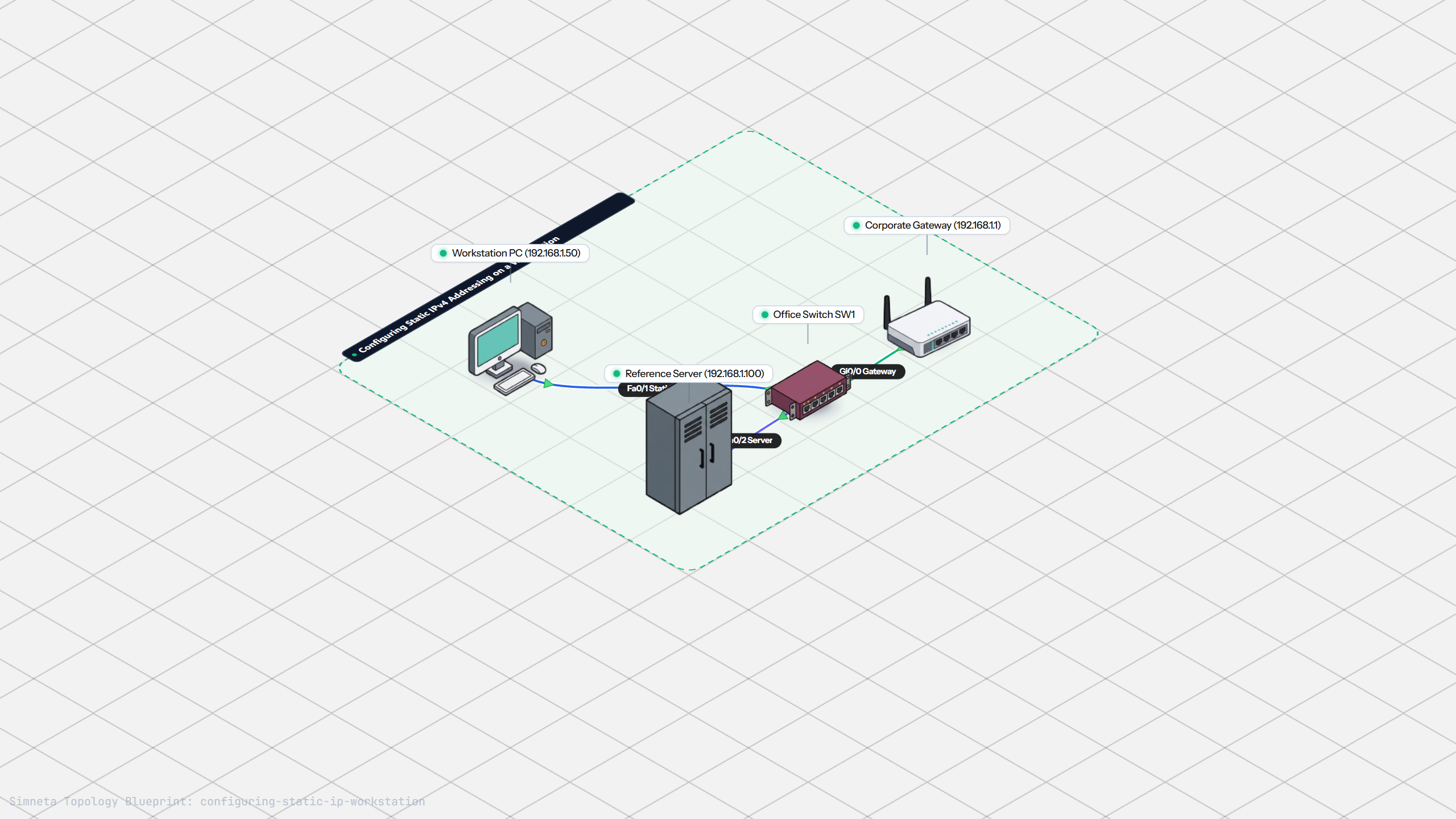
Configuring Static IP on Workstation
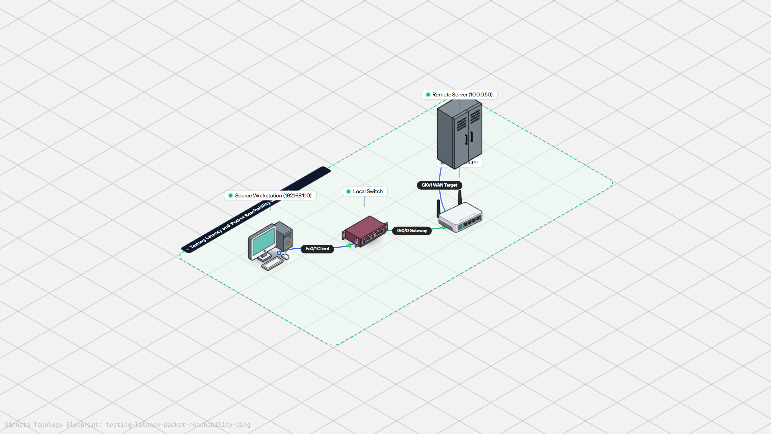
Testing Reachability and Latency with Ping
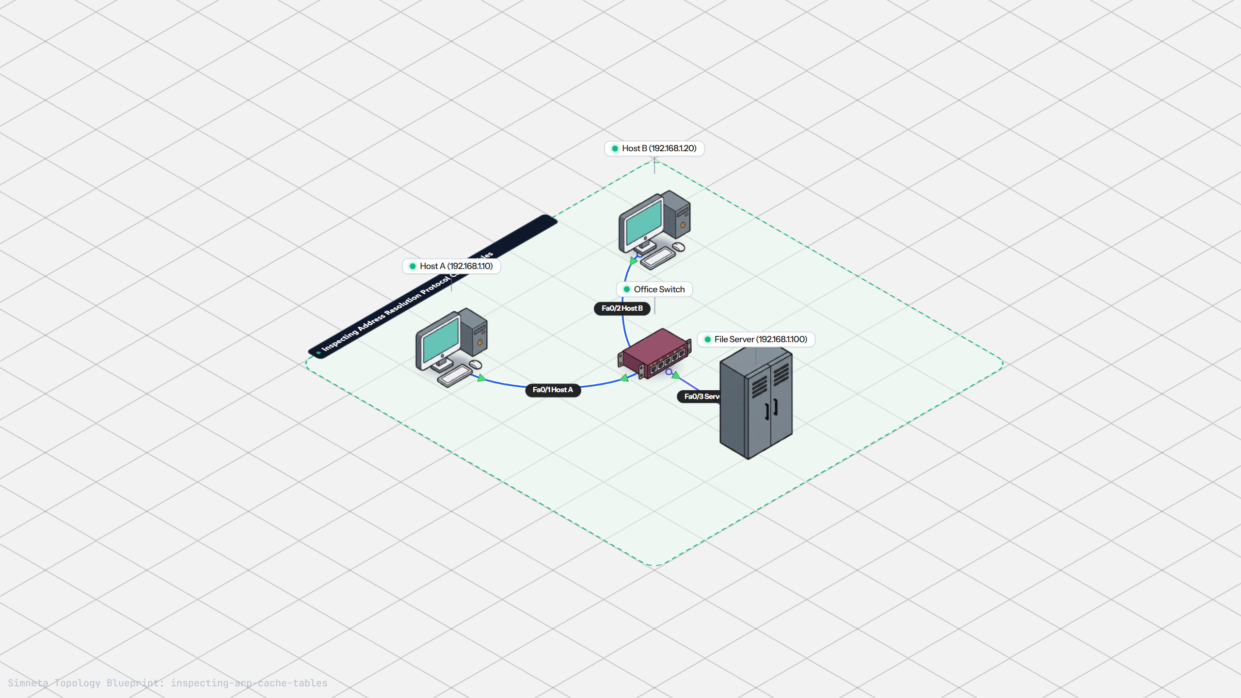
Inspecting ARP Cache Tables
Setting Up DHCP Static Reservations
Configuring Default Static Route to ISP
Blocking Ping with Standard ACL
Port Forwarding for Web Servers
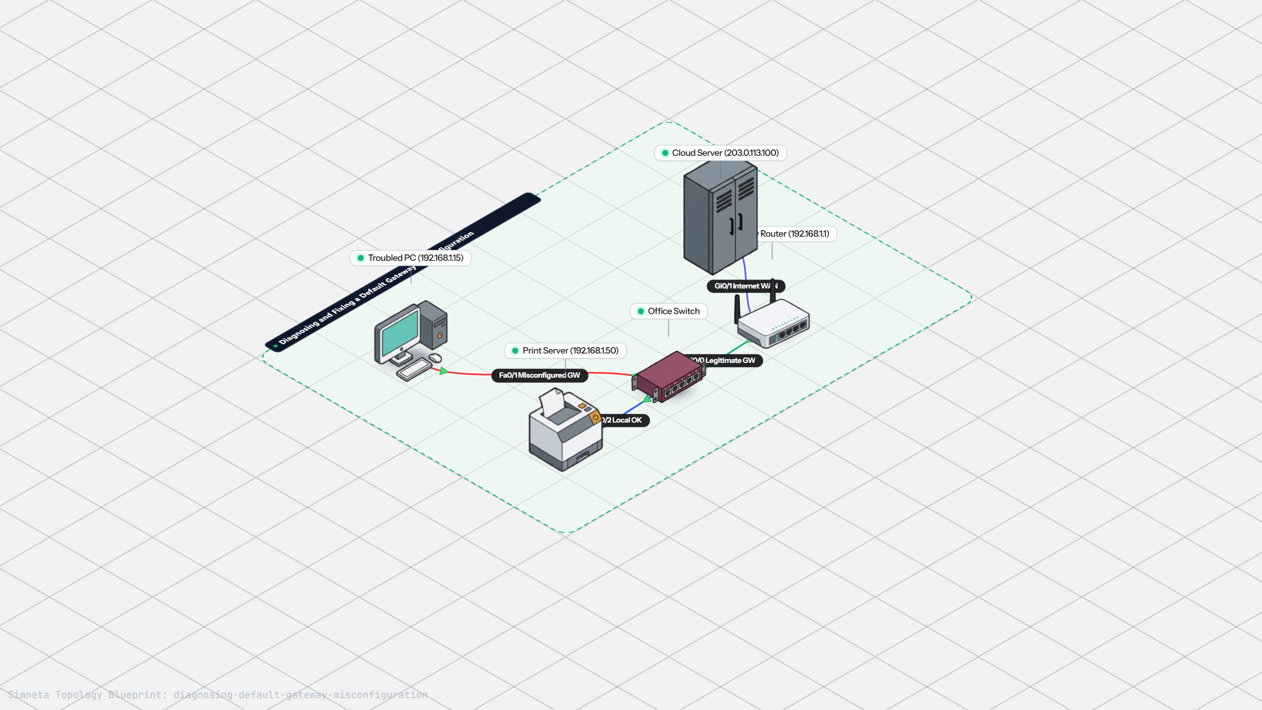
Fixing Default Gateway Misconfigurations
Discussion & Community Notes
Ask questions, share configuration tips, or discuss this laboratory topology.